Simulation of High-Pressure Spray Flames III
 Sandro_Gierth_Simulation of high-pressure spray flames_Figure1
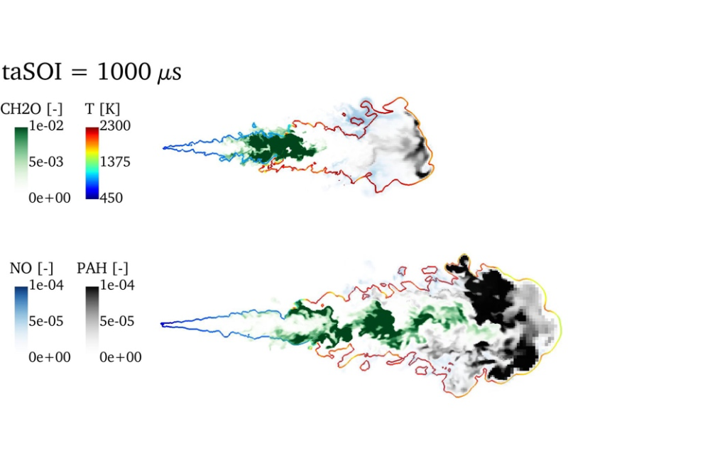
Figure 1: The structure of the ECN Spray A (top) and ECN Spray D (bottom) from mixture formation to gaseous pollutant formation. The contour denotes stoichiometric conditions color-coded by the temperature.
Sandro GierthIntroduction
The formation of pollutants in direct injection engines is a field of research with high practical impact. Against this background, this project deals with the simulation of high-pressure spray injection and the subsequent ignition and pollutant formation, i.e., soot and NOx. Since these processes are strongly determined by the mixing processes of the evaporated liquid fuel with the gaseous environment, Large Eddy Simulations of the turbulent flow developing during the injection process are performed. The results of these detailed simulations are used to analyze the cause-effect chain in pollutant formation in high-pressure spray flames and serve as reference data for the adaption of models with lower computational cost but higher amount of empirical model parameters.
Methods
The dispersed liquid phase arising from disintegration of liquid fuel near the nozzle is described by a statistical representation in terms of a number density function. This is discretized by stochastic particle in the current investigation, i.e., parcel representing a certain number of droplets with equal quantities. The underlying continuous gas-phase is described by the conservation equation for mass, momentum and enthalpy in an Eulerian frame of reference which are discretized by means of the Finite Volume Method. Coupling between both phases is obtained by source terms, incorporating non-resolved exchange processes like drag and mass transfer. The ignition and combustion process remain unresolved at its smallest scales. Since combustion chemistry is fast and takes place in thin flame-sheets in the current application, equations for the flame structures can be solved decoupled from the 3D-CFD within an in-house C++ code [1] and its solutions are assembled within a look-up table for read-into the CFD by parametrizing the flame structure by a reduced set of control variables.
Results
In the current project phase, the ECN Spray A injector was investigated by means of Large Eddy Simulations in a reactive environment. An extended version of the utilized combustion model to capture the formation of species at different time scales was proposed and validated. This approach was further used to simulate the ECN Spray D injector, with a nozzle hole diameter relevant for heavy-duty applications. For both injectors, experimental measurements in terms of vapor and liquid penetration lengths, global ignition characteristics as well as Planar laser-induced fluorescence data are well reproduced with the simulation strategy. The latter in particular show the suitability of the approach to describe the local flame structure as well as the formation of gas-phase pollutant species and enabled a comparison of the flame structure of sprays originating from injectors with different nozzle sizes.
Discussion
Due to their molecular structure, the ignition of long-chained hydrocarbon fuels is taking place in at least two stages. After the production of first radicals from the fuel molecules, formaldehyde (CH2O) is formed in fuel lean regions under most reactive conditions which is connected with a moderate increase in temperature. By means of molecular and turbulent transport, this temperature rise leads to a heat flux to adjacent fuel/air mixtures, initiating the onset of ignition there. This process is called cool flame propagation as introduced by Dahms et al. 2017. After sufficiently large residence times, the second stage of the ignition process is taking place where CH2O is consumed connected with a strong increase in temperature and OH mass fraction for mixtures near stoichiometric conditions. Subsequently, the formation of species at large time scales, e.g., NOx and soot precursor, is taking place. While the former is mainly formed in near stoichiometric regions, the latter one can be found in fuel rich parts of the spray flame. Due to the different mass and momentum flow rates, the sprays show a different mixing behavior. In particular, the ECN Spray D shows a larger fuel rich core of the vaporized fuel. As mentioned above, this influences the spatial flame structure and the distribution of pollutant species. This manifests itself in a different ignition location. In particular, an ignition at the spray head is observed for the ECN Spray A and on the spray flanks in case of the ECN Spray D. This behavior is well known from literature and was successfully reproduced by the utilized simulation approach. After the flame establishes, the structure of pollutants is affected by the mixture formation, too, as shown in Figure 1. In case of the ECN Spray A, a clear axial separation of CH2O and pollutant species is observed. In contrast, a radially stacked structure is observed for the ECN Spray D with CH2O located at the centerline, followed by soot precursor and subsequently NO at the borderline of the spray flame. With increasing axial distance to the nozzle, CH2O is consumed and soot precursor are also observed on the center line of the vaporized fuel jet.