Deriving of Design Guidelines for Cold Flow Combustors Based on Flow Phenomena in Combustors Under Real Operating Conditions
Introduction
A jet engine’s high-pressure turbine, which is located downstream of the combustor, is subject to an extremely high turbulence intensity. The average intensity at the turbine entry can exceed 20% with greatly anisotropic behaviour. This has a significant impact on the turbine’s aerothermal behaviour. It is therefore important to understand and to be able to recreate such inflow conditions in cold turbine test rigs to better investigate and improve turbine blade and cooling designs.
Different methods exist to generate turbulent inflow conditions at turbine rigs. However, most of them are unable to recreate engine-representative turbulence intensity while maintaining engine-representative turbulent length-scales and anisotropy. Therefore, combustor simulators are necessary if all aspects mentioned are desired.
This project aims to derive design guidelines for such combustor simulators for modern rich-burn, quick-quench, lean-burn combustion chambers. This is done numerically using computational fluid dynamics. Since the turbulent behaviour in the combustion chamber is greatly anisotropic, steady Reynolds-averaged Navier-Stokes simulations must be supplemented with scale-resolving simulations. Latter are also used to examine the steady simulations’ applicability. Additionally, different geometry and operating point variations are necessary in order to investigate the turbulent structures inside the combustor. This means that great computational resources are required which can be found at the NHR4CES high performance computer.
Methods
The simulations in this project are performed using PRECISE-UNS which is a cell-based finite volume CFD solver developed by Rolls-Royce. Its main capabilities and specialisation lie in the simulation of aero-engine combustors. In this project different turbulence models were used within PRECISE-UNS. Steady Reynolds-averaged Navier Stokes simulations allow for quick geometry variations and additionally serve as the initial conditions for transient simulations. The steady simulations are coupled with the κ – ω realisable model for the turbulence treatment. For the transient simulations, scale-resolving large eddy simulations are conducted.
In case of reactive simulations, the flamelet generated manifold approach is used for the combustion modelling. The fuel is injected at prescribed positions in the domain using a spray model combined with a Lagrangian particle tracking method.
Results
First, large eddy simulations were conducted for a baseline modern engine-representative rich-burn, quick-quench, lean-burn combustion chamber. This is done for a reactive and an isothermal case. For the reactive case, the boundary conditions are set to match the engine’s take-off conditions. In the isothermal simulations, the fuel mass flow is omitted, and the solver also omits solving the energy equation in order to reduce the computational costs.
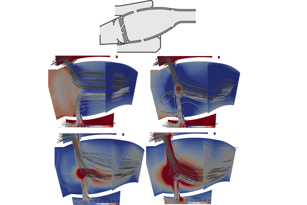
The direct comparison of the reactive and isothermal case reveals a significant increase in turbulent intensity at the combustor’s exit and thus the turbine’s entry. The average value at the turbine’s inlet increases by 44% in the isothermal case compared to the reactive case. The majority of velocity fluctuation and thus turbulence intensity is generated by the interaction of the mixing jets with themselves and with the main flow. The mixing jets are introduced via ports in the combustor’s inner and outer liner. They are necessary for rapid mixing of the fuel-air mixture with fresh air which can be called quenching.
The increase of turbulent intensity at the turbine’s entry in the isothermal case can also be traced to changes in the mixing jets. The absence of the combustion shifts more mass towards the mixing jets meaning their relative velocity and penetration depth are increased. This leads to the increased turbulent intensity. Such combustion chamber designs can therefore not be used isothermally in test rigs to generate engine- representative conditions. They have to be modified in some way.
To further investigate this, the combustor’s geometry is gradually simplified in order to understand the influence of different geometric features, find possible simplifications for developing a combustor simulator and most importantly lower the turbulence intensity to a representative level.
It was found that the key factor for achieving similar turbulence levels is a similar velocity ratio of jet velocity to combustor exit velocity. This means that jets’ velocities have to be reduced in the same manner as the averagevelocity at the combustor exit is reduced due to the missing thermal expansion. This can be achieved by either lowering the mixing jets’ mass flow or by increasing the ports’ diameter. The latter can have an influence on the initial jet angle which might have unwanted effects and has to be used with this in mind.
Discussion
The data obtained during this research project suggest that – contrary to conventional combustors – rich-burn, quick-quench, lean-burn combustors should not be used unmodified for cold flow test rigs. The obtained turbulence intensity was not engine representative. Design considerations for a cold flow combustor simulator were provided which now wait to be tested experimentally.


