Competence Development of Engineering Methodology for the Design of Centrifugal Compressors
 Haeckel, Tobias_Competence Development of Engineering Methodology for the Design of Centrifugal Compressors
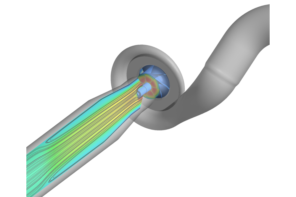
Figure 1: Compressor inlet recirculation for an operating point close to the surge limit.
Tobias HaeckelIntroduction
A decisive property of centrifugal compressors for turbochargers is the map width, which defines the area of the compressor map in which it can be operated stably. A large map width is decisive to achieve sufficient (internal combustion) engine dynamics and thus acceleration of the vehicle as well as maximum fuel savings. Towards large mass flows, the map is limited by the choke limit and to small mass flows by the surge limit. The choke limit can be reliably determined using steady-state 3D-CFD-simulations. Determining the surge limit by means of simulations is much more demanding and has been a research topic for decades. As part of this project, a methodology for determining the surge line using 3D-CFD-simulations is to be developed.
Methods
For all CFD calculations the commercial CFD-code Ansys CFX is used. Within CFX the threedimensional, coupled, pressure based flow solver is applied to solve the Reynolds-averaged compressible Navier-Stokes equations. The solver is based on the finite volume method and uses a high-resolution scheme (quasi-2nd order) for spatial discretization. The closure problem of the Reynolds-averaged Navier-Stokes equations is treated by Menter’s SST model which combines the advantages of the k-ϵ model in free streams and the k-ω model near walls and additionally considers the effect of the transport of the turbulent shear stress. The interface between rotating and stationary components is treated by the sliding mesh approach.
Results
Characteristic flow phenomena of radial compressors at low mass flow rates are secondary flow phenomena. These flows superimpose the flow in the actual streamwise direction given by the blade and casing geometry. Depending on the strength of the secondary flow, the flow direction of the secondary flow might even reverse and result in a recirculating bubble at the compressor wheel inlet. The recirculation is then a major source of losses. Through the opposing flow directions of the recirculating flow and the active flow a distinct shear layer develops. This shear layer is the source of multiple tornado-like shaped vortices which are travelling through the impeller passage. This is affecting the pressure rise and results in a fluctuating pressure at the compressor outlet, which can trigger compressor instability.
Discussion
On the one hand we have explored time-dependent vortex phenomena, which are a reason for compressor instability. On the other hand, the simulations were very time-consuming. For this reason, the current method is suitable primarily for research rather than the industrial development process. To overcome this weakness, further research should be done with respect to speeding up the simulations. In the case of research, the next step would be an investigation on how to specifically influence the appearance and intensity of the mentioned vortex phenomena by compressor wheel design parameter.