Lufo 5 PRESTIGE
 Lufo 5 PRESTIGE1
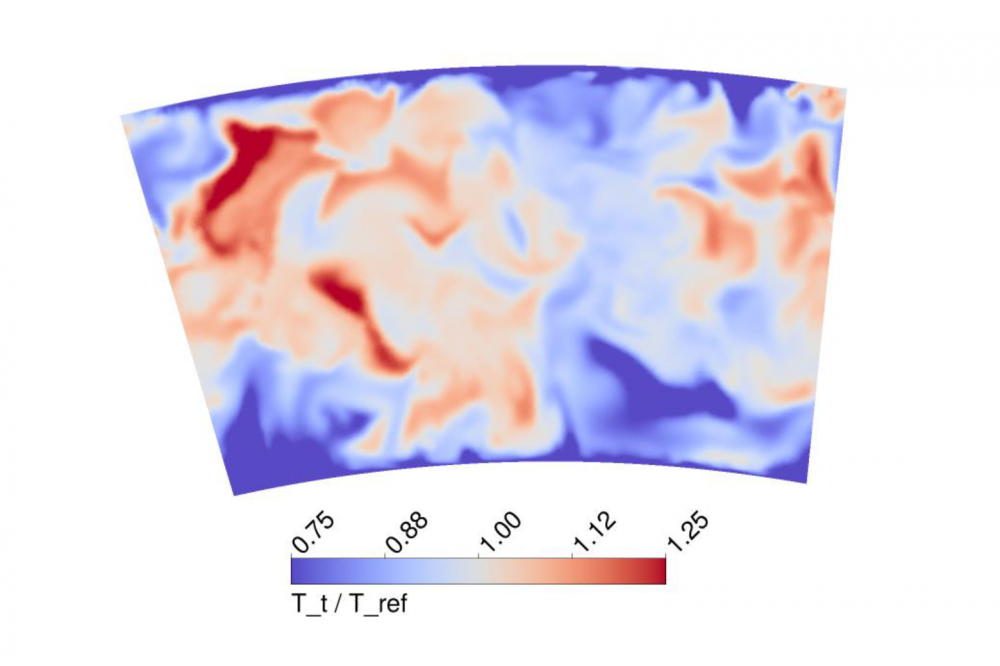
Figure 1: Snapshot of fluctuating temperature field at the inlet of the turbine domain.
Jonathan Gründler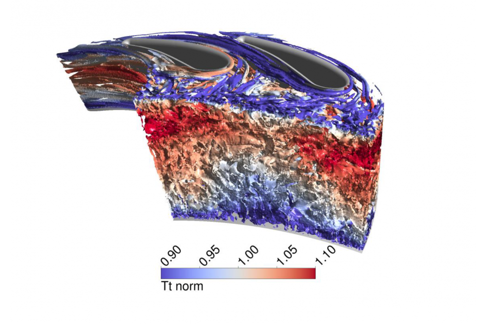 Lufo 5 PRESTIGE2
Figure 2: Vortex structures in NGV passage visualized with the Q-criteria and coloured by the standardized total temperature.
Jonathan GründlerIntroduction
The high pressure turbine design is strongly affected by the flow in the upstream combustor. Very high temperatures, large flow angles and high levels of turbulence decrease the turbine efficiency and raise the demand for an efficient turbine cooling design. To design the turbine to the lifetime requirements and to optimum efficiency it is of very high importance to understand the interaction mechanisms between combustor and turbine and to take all the important combustor related effects into account. When it comes to investigating the combustor turbine interaction (CTI), numerical simulation have a very important role since experimental measurements are very limited and expensive. The standard procedure for numerical simulations in the context of CTI is a decoupled approach. Combustor and Turbine are treated in separate simulations and 2D mean field data is passed over at the interface. By doing so, unsteadiness coming from the combustor is not taken into account in the turbine simulation. In general the effect of combustor unsteadiness on the high pressure turbine is not yet well understood and is not included into the common design process. Transient turbine simulations with scale resolving turbulence models are needed to get a better understanding of the underlying physical mechanisms. For these simulations unsteady boundary conditions need to be created which represent the actual flow in the combustor in the best possible way.
Methods
A method for unsteady 1-way coupling of combustor and turbine is under investigation. The aero-thermal analysis of the first NGV of the high pressure turbine is done by using 3D CFD. To resolve the unsteadiness coming from the combustor, a transient simulation setup and scale resolving turbulence models like SAS (Scale Adaptive Simulation) are used. For the generation of unsteady boundary conditions, the method of digital filter is used to superpose fluctuations to an existing mean field.
Results
First simulations show the ability of the method to prescribe turbulent fluctuations as inlet boundary condition of a transient turbine simulation. They also point out the two main problems with this method.
1. Large number of time steps necessary for convergence of inlet field
2. Large discrepancy in time step width between inlet boundary condition from digital filter and turbine simulation
Discussion
To overcome the two main issues of the presented method, in the next project period a data compression method using POD (Proper Orthogonal Decomposition) is going to be included into the unsteady 1-way coupling of combustor and turbine.