Flexible HP-Turbines III
 Linne_Marius_Flexible HP-Turbines III_Fig2
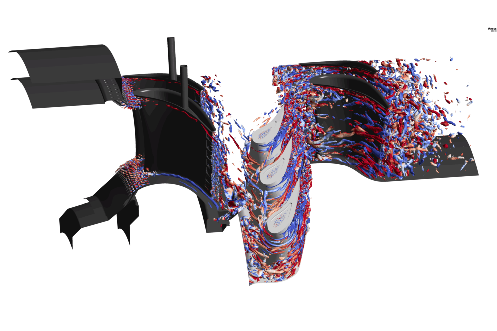
Figure 2: SBES: Q criterion colored in vorticity
Marius LinneEinleitung
Over the last decades, turbomachinery has been subject of continuous improvement and fundamental research within the combined fields of fluid and thermodynamics. Consequently, minor improvements in efficiency are linked to the highest requirements in component design. However, the aerodynamic design process of high-pressure turbines (HPTs) is heavily reliant on the prediction capabilities of 3D computational fluid dynamics (CFD) simulations due to the lack of experimental data. Although computational resources are steadily increasing and more sophisticated turbulence models are becoming more available, the industrial state-of-the-art turbulence modelling approach is still based on Reynolds-Averaged Navier-Stokes (RANS) methods. While the effect of scale-resolving simulations (SRS) on the thermal prediction capabilities in an HPT stage has been subject to numerous studies, the aerodynamic potential has not been fully validated yet, especially when effects of blade-row interaction are of interest. The numerical simulations shall be validated against experimental measurements in the Large Scale Turbine Rig (LSTR) located at the Institute for Gas Turbines and Aerospace Propulsion at Technical University of Darmstadt.
Methoden
For the unsteady and scale-resolving simulations in this project the commercial CFD code CFX from ANSYS is used. It is an industrial CFD software tool that delivers solutions across a wide range of CFD applications and is specialized in turbomachinery problems. The ANSYS CFX solver uses a finite volume approach to solve the system of equations. The spatial discretization of the advection term is done by using a bounded central differencing scheme (CDS). For temporal discretization, an implicit second-order formulation is used. Within the simulations in this project, different turbulence modelling approaches are used. To provide initial conditions, steady-state RANS simulations are conducted. The realization of a fully wall-resolving Large Eddy Simulation (LES) is not yet possible due to the high Reynolds number in the HPT and the consequent mesh size and time-step restrictions. For this project, Stress-Blended Eddy Simulation (SBES) is used. The SBES is classified as a Detached-Eddy Simulation (DES). These models are hybrid LES/RANS approaches, where LES is used in the free flow and RANS at the walls, where the mesh resolution is insufficient for LES. A shielding function switches between the LES and RANS regimes.
Ergebnisse
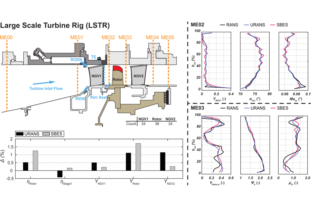
The purpose of this project is to show and highlight the effects and challenges of scale-resolving turbulence models on the simulation of the 1.5-stage LSTR. The Reynolds number in the LSTR is equal to a real high-pressure turbine so that nearly all flow phenomena as well as computational efforts are identical. The main purpose of this project is the derivation of a highly accurate numerical setup and its validation against experimental data. However, due to problems regaarding the test rig and the strong dependency on its data, which is usually used as a boundary condition for the CFD, not all simulations could be conducted. Therefore, only a first comparison could be drawn between the standard RANS simulation, the more sophisticated URANS simulation and the most high-fidelity SBES simulation. The LSTR setup as well as the first numerical results can be seen in Fig. 1 as a 0D comparison of selected performance parameters as well as radial profiles of the flow quantities in the rotor inlet (ME02) and outlet (ME03) plane. As the flow enters the turbine, it interacts with the hub (RIDN) and casing (RODN) side platform film cooling ejections of the first Nozzle Guide Vane (NGV1). Within the NGV1 passage the flow is accelerated and turned in circumferential direction to provide angular momentum to the flow that can be extracted by the rotor. In ME02 (Fig. 1, top right) the first deviations can be seen between the RANS and the URANS simulations, that both use the k-ω-SST turbulence model. The only difference between these approaches is the treatment of time. While the time is neglected in the RANS (steady-state), it is fully resolved in the URANS, and therefore effects of stator-rotor-interaction. These seem to affect the flow mostly in the lower 20 % of the channel and seem to cause a higher pressure loss as well as higher turning and therefore a reduced mass flow. Higher deviations occur between the URANS and the SBES simulation. Compared to the RANS approaches, the SBES and its LES formulation in the free stream appear to predict a different mixing of the main with the cooling flow of the trailing edge (TE) slot ejection, which can be seen in the more wavy appearance of the flow quantities in the region from 20 % to 85 % channel height.
In ME03 (Fig. 1, bottom right) the deviations between the different approaches become far more pronounced. This can mainly be drawn back to the fact that the simulation of a rotor in turbomachinery is subject to high numerical uncertainties due to the assumptions made in steady-state RANS simulations. Therefore, high deviations can be seen between RANS and URANS, mainly in the mass flow redistribution μ21 in the lower 40 % of the channel. This shows that in order to be accurate in the simulation of a high-pressure turbine, the higher computation costs of a URANS seem to be justified. The deviations between URANS and SBES are highest in the rotor tip region above 70 % channel height. Due to the radial gap between rotor tip and the casing, a vortex rolls up, that causes high losses and blockage. The region of this Tip Leakage Vortex usually shows the highest amounts of turbulent viscosity μt and therefore a portion of modelling in the flow. Due to the LES formulation in the SBES this modelling can be reduced by a significant amount.
Diskussion
Overall, the SBES turbulence model shows a higher efficiency (Fig. 1, bottom left) for the rotor as well as for the first stage compared to the RANS and the URANS simulation. For a full validation, the comparison with experimental data is extremely important in order to judge whether the much higher costs of an SBES are justified or not. However, it shall also be noted that URANS and SBES simulations were performed on the same mesh. The formulation of the shielding function in the SBES is also dependent on mesh resolution, so a finer mesh could potentially yield different results due to the lower amount of RANS modelling. This needs to be addressed in future investigations as well as the sensitivity to small changes in the rotor inlet flow field due a different operating point and a study of the influence of the time-step size.